IPv6 has been something I have long championed, ever since establishing the first tunnels in the last 1990’s when I was working at UWA. Its also something I was pushing to AWS Service Delivery teams when I worked at AWS in the early 2010s, and in my time at Ajilon/Modis/Akkodis, I have set IPv6 as a stretch goal for all AWS projects to support as a standard.
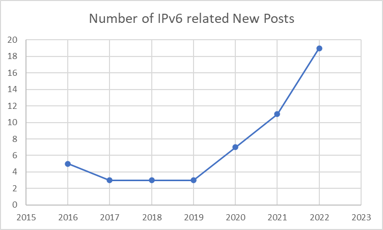
What’s interesting to see is the increase in IPv6 related announcements from ASW in the What’s New page by year:
Number of IPv6 related posts on AWS What’s New page, as at 19 Dec 2022.
It’s clear that IPv6 is now a first class citizen. Coverage is pretty strong, and customers not only can, but in my opinion should, be targeting dual stack solutions, or in some use cases, IPv6-only deployments.
As System Operators (Sys Admins), DevOps and Developer folk, you should be fully comfortable with another transport protocol. Any considerations around addressing should be minimal. In the on-premises desktop/end-user-compute environment, your internal networks are possibly all IPv4 only, but your corporate proxy should now be dual-homed. (It should also be supporting TLS 1.3 and HTTP/3).
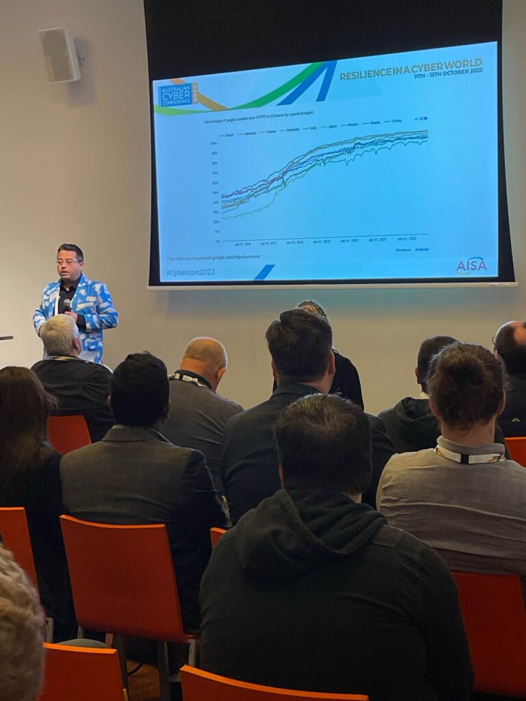
I’ve been talking for the last number of years about some of the web security changes that have happened in the web/browser/PKI landscape, many of which have happened quietly and those not paying attention may have missed.
One very interesting element has been a modern browser capability called Network Error Logging. Its significant as it fixes a problem in the web space where errors may happen on the client side, and the server side hears nothing about it.
Adopting NEL is another tool in your DevOps armoury, to drive operational excellence and continuous improvement of your deployed web applications, helping to retain customers and increase business value.
Essentially, this is a simple HTTP header string that can be set, and browsers that recognise it will cache that information for a period (that you specify). If the browser has any of a whole set of operational issues while using your web site, then it has an opportunity to submit a report to your error logging endpoint (or cache it to submit later).
Prior to this, you would have to rely on the generosity of users reporting issues for you. The chance of a good Samaritan (white hat) getting through a customer support line to report issues is.. small! Try calling your local grocery store and tell them they have a JavaScript error. Indeed, for this issue, we have RFC 9116 for security.txt.
Having your users report your bad news is kind of like this scene from the 1995 James Bond film GoldenEye:
“Unlike the American Government we prefer not to get our bad news from CNN” – M, GoldenEye
So, what’s the use-case of Network Error Logging. I’ll split this into four scenarios:
Developer environments
Testing environments
Non-production UAT environments
Production Environments
Developer Environments
Developers love to code, and will produce vast amounts of code, and have it work in their own browser. They’ll also respond to error sin their own environments. But without the NEL error logs, they may miss the critical point a bug is at, when something fails to render in the browser.
NEL gives developers the visibility they are lacking when they hit issues, with otherwise, need screen captures from the browser session (which are still useful, particularly if your screen capture includes the complete time (including seconds) and the system is NTP synchronised).
With stricter requirements coming (such as Content Security Policies being mandated by the PCI DSS version 4 draft on payment processing pages), the sooner you can give developers the visibility of why operations have failed, the more likely of success when the software project makes it to a higher environment.
So, developers should have a non-production NEL endpoint, just to collect logs, so they can review and sort them, and affect change. Its not likely to be high volume reporting here – it’s just your own development team using it, and old reports are quickly worthless (apart from identifying regressions).
Testing Environments
Like developers, Test Engineers are trying to gather evidence of failures to feed into trouble ticketing systems. A NEL endpoint gives Testers this evidence. Again the volume reporting may be pretty low, but the value of the reporting will again help errors hitting higher environments.
Non-Production UAT Environments
This is your last chance to ensure that the next release into production is not hitting silly issues. The goal here to is make the volume of NEL reports approach zero, and any that come in are likely to be blockers. Depending on the size of your UAT validation, the volume will still be low.
Production Environments
This is where NEL becomes even more important. Your Security teams and your operational teams need to both have real-time visibility of reporting, as the evidence here could be indicative of active attempts to subvert the browser. Of course the volume of reports could also be much larger, so be prepared to trade the fraction of reporting to balance the volume of reports. It may also be worth using a commercial NEL endpoint provider for this environment.
Running your own NEL Endpoint
There is nothing stopping you from running your own NEL endpoint, and this is particularly useful in low volume, non-production scenarios. It’s relatively, simple, you just need to think of your roll out:
Let every project define their own NEL endpoints, perhaps one per environment, and let them collect and process their own reports
Provide a single central company-wide non-production NEL endpoint, but then give all developers access to the reports
Somewhere in the middle of these above two options?
Of course, none of these are One Way Doors. You can always adjust your NEL endpoints, by just updating the NEL headers you have set on your applications. If you don’t know how to adjust HTTP header strings on your applications and set arbitrary values, then you already have a bigger issue in that you don’t know what you’re doing in IT, so please get out of the way and allow those who do know to get stuff done!
Your NEL endpoint should be defined as a HOSTNAME, with a valid (trusted) TLS certification, listening for an HTTP post over HTTPS. Its a simple JSON payload, that you will want to store somewhere. You have a few choices as to what to do with this data when submitted:
Reject it outright. Maybe someone is probing you, or submitting malicious reports (malformed, buffer overflow attempt, SQL injection attempt, etc)? But these events themselves may be of interest…
Store it:
In a relational database
In a No-SQL database
In something like ElasticSearch
Relay it:
Via email to a Distribution List or alias
Integration to another application or SIEM
My current preference is to use a No-SQL store, with a set retention period on each report.
NEL in AWS API Gateway, Lambda and DynamoDB
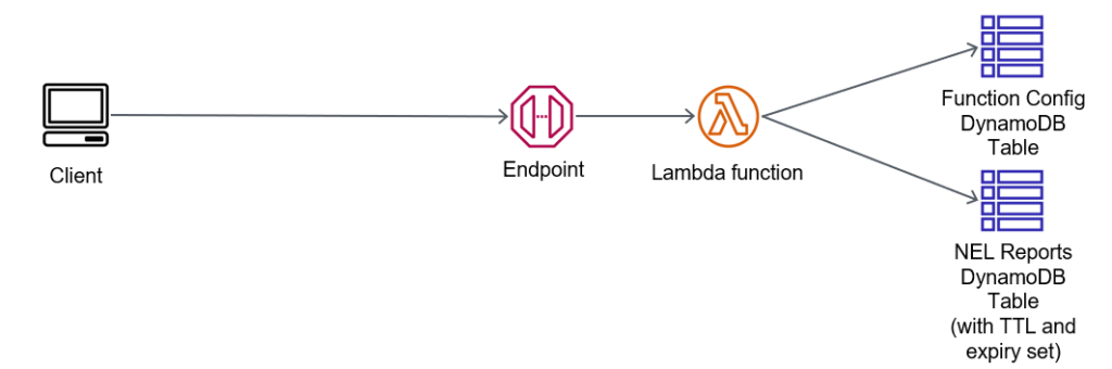
The architecture for this is very simple:
Simple NEL endpoint with API Gateway, Lambda and DynamoDB
We have one table which controls access for reports to be submitted; its got config items that are persistent. I like to have a config for banned IPs (so I can block malicious actors), and perhaps banned DNS domains in the NEL report content. Alternately, I may have an allow list of DNS domains (possibly with wildcards, such as *.example.com).
My Lambda function will get this content, and then evaluate the source IP address of the report, the target DNS domain in the report, and work out if its going to store it in the Reports table.
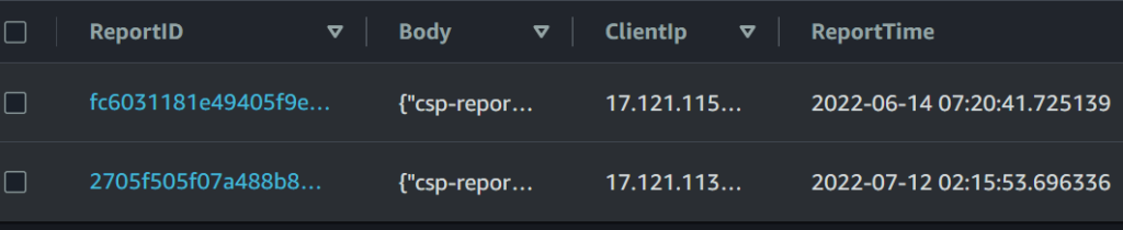
When inserting the JSON into the report table, I’m also going to record:
The current time (UTC)
The source address the report came from
Here’s an example report that’s been processed into the table:
And here is the Lambda code that is validating the reports:
import json
import boto3
import ipaddress
import datetime
import uuid
def lambda_handler(event, context):
    address = report_src_addr(event)
    if address is not False:
        if report_ip_banned(address) or not report_ip_permitted(address):
            return {
                'statusCode': 403,
                'body': json.dumps({ "Status": "rejected", "Message": "Report was rejected from IP address {}".format(address)})
            }
    if not report_hostname_permitted(event):
        return {
            'statusCode': 403,
            'body': json.dumps({ "Status": "rejected", "Message": "Reports for subject not allowed"})
        }
    report_uuid = save_report(event)
    if not report_uuid:
        return {
            'statusCode': 403,
            'body': json.dumps({ "Status": "rejected"})
            }
    return {
        'statusCode': 200,
        'body': json.dumps({ "Status": "accepted", "ReportID": report_uuid})
    }


def save_report(event):
    report_uuid =  uuid.uuid4().hex
    client_ip_str = str(report_src_addr(event))
    print("Saving report {} for IP {}".format(report_uuid, client_ip_str))
    response = report_table.put_item(
        Item={
            "ReportID": report_uuid,
            "Body": event['body'],
            "ReportTime": str(datetime.datetime.utcnow()),
            "ClientIp": client_ip_str
            }
        )
    if response['ResponseMetadata']['HTTPStatusCode'] is 200:
        return report_uuid
    return False


def report_ip_banned(address):
    fe = Key('ConfigName').eq("BannedIPs")
    response = config_table.scan(FilterExpression=fe)
    if 'Items' not in response.keys():
        print("No items in Banned IPs")
        return False
    if len(response['Items']) is not 1:
        print("Found {} Items for BannedIPs in config".format(len(response['Items'])))
        return False
    if 'IPs' not in response['Items'][0].keys():
        print("No IPs in first item")
        return False
    ip_networks = []
    for banned in response['Items'][0]['IPs']:
        try:
            #print("Checking if we're in {}".format(banned))
            ip_networks.append(ipaddress.ip_network(banned))
        except Exception as e:
            print("*** EXCEPTION")
            print(e)
            return False
    for banned in ip_networks:
        if address.version == banned.version:
            if address in banned:
                print("{} is banned (in {})".format(address, banned))
                return True
    #print("Address {} is not banned!".format(address))
    return False


def report_ip_permitted(address):
    fe = Key('ConfigName').eq("PermittedIPs")
    response = config_table.scan(FilterExpression=fe)
    if len(response['Items']) is 0:
        return True
    if len(response['Items']) is not 1:
        print("Found {} Items for PermittedIPs in config".format(len(response['Items'])))
        return False
    if 'IPs' not in response['Items'][0].keys():
        print("IPs not found in permitted list DDB response")
        return False
    ip_networks = []
    for permitted in response['Items'][0]['IPs']:
        try:
            ip_networks.append(ipaddress.ip_network(permitted, strict=False))
        except Exception as e:
            print("permit: *** EXCEPTION")
            print(e)
            return False
    for permitted in ip_networks:
        if address.version == permitted.version:
            if address in permitted:
                print("permit: Address {} is permitted".format(address))
                return True
    print("Address {} not permitted?".format(address))
    return False

def report_hostname_permitted(event):
    if 'body' not in event.keys():
        print("No body")
        return False
    if 'httpMethod' not in event.keys():
        print("No method")
        return False
    elif event['httpMethod'].lower() != 'post':
        print("Method is {}".format(event['httpMethod']))
        return False
    if len(event['body']) > 1024 * 100:
        print("Body too large")
        return False
    try:
        reports = json.loads(event['body'])
    except Exception as e:
        print(e)
        return False

    for report in reports:
        print(report)
        return True
        if 'url' not in report.keys():
            return False
        url = urlparse(report['url'])
        fe = Key('ConfigName').eq("BannedServerHostnames")
        response = config_table.scan(FilterExpression=fe)
        if len(response['Items']) == 0:
            print("No BannedServerHostnames")
            return True
        for item in response['Items']:
            if 'Hostname'not in item.keys():
                continue
            for exxpression in item['Hostname']:
                match = re.search(expression + "$", url.netloc)
                if match:
                    print("Rejecting {} as it matched on {}".format(url.netloc, expression))
                    return False
    return True


def report_src_addr(event):
    try:
        addr = ipaddress.ip_address(event['requestContext']['identity']['sourceIp'])
    except Exception as e:
        print(e)
        return False
    #print("Address is {}".format(addr))
    return addr


def parse_X_Forwarded_For(event):
    if 'headers' not in event.keys():
        return False
    if 'X-Forwarded-For' not in event['headers'].keys():
        return False
    address_strings = [x.strip() for x in event['headers']['X-Forwarded-For'].split(',')]
    addresses = []
    for address in address_strings:
        try:
            new_addr = ipaddress.ip_address(address)
            if new_addr.is_loopback or new_addr.is_private:
                print("X-Forwarded-For {} is loopback/private".format(new_addr))
            else:
                addresses.append(new_addr)
        except Exception as e:
            print(e)
            return False
    return addresses
You’ll note that I have a limit on the size of a NEL report – 100KB of JSON is more than enough. I’m also handling CIDR notation for blocking (eg, 130.0.0.0/16).
Operational Focus
Clearly to use this, you’ll want to push the Lambda function into a repeatable template, along with the API Gateway and DynamoDB table.
You may also want to have a Time To Live (TTL) on the Item being submitted in save_report() function, with perhaps the current time (Unix time) plus a number of seconds to retain (perhaps a month), and configure TTL expiry on the DynamoDB table.
You may also want to generate some custom CloudWatch metrics, based upon the data being submitted; perhaps per hostname or environment, to get metrics on the rate of errors being reported.
Summary
Hopefully the above is enough to get you to understand NEL, and help capture these reports from your web clients; in a production environment you may want to look at report-uri.com, in non-production, you may want to roll your own as above.
I have previously spoken at the AISA local Perth branch conference, and figured that there was a lack of content around my area of interest, being web security (something I have spoken at other conferences in the past about, and been teaching students and colleagues since 2014.
I was thrilled to be selected, based on merit (and not sponsorship), to present.
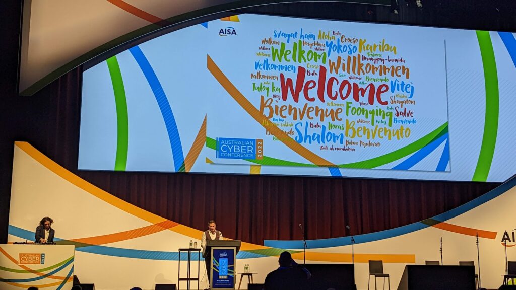
Damien Manuel, AISA Chair and Adjunct Professor at Deakin University opening CyberConf 2022
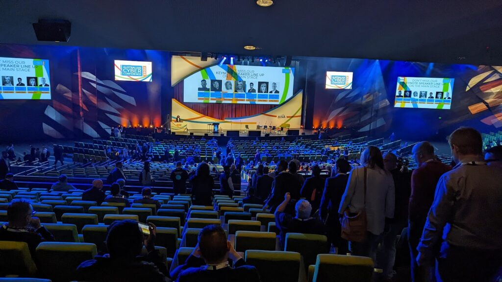
Held at the Melbourne Convention and Exhibition Centre, spanning three floors, there weer to be just shy of 400 speakers, and over 4000 attendees.
MCEC Main Auditorium, with 5000 seat capacity, with delegates starting to file in…
Its a big venue, and there were at times some 15 simultaneous breakout streams running over the three days of the conference, along with a large exhibitor hall. The catering budget alone for the event was in excess of AU$1M.
James Bromberger, listening to the opening presentations and keynote at CyberConf 2022
We started with a word from Clare O’Neil, the federal minister presenting via pre-recorded video:
Clare O’Neil
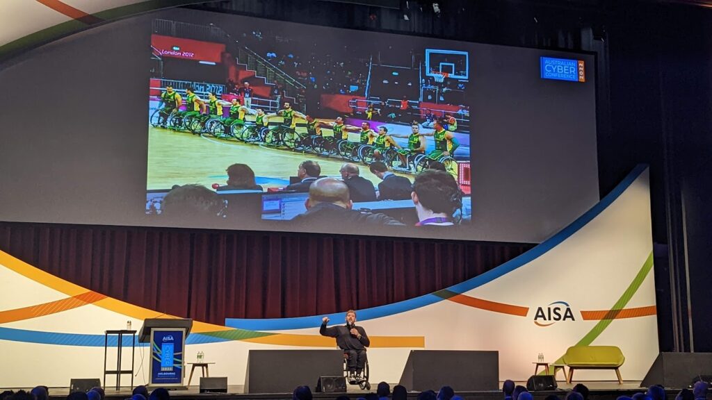
This was followed by Dillan Alcott giving a no-holes bared authentic blast from his personality on how he sees himself, his challenges, and opportunities:
Dillan Alcott at CyberConference 2022
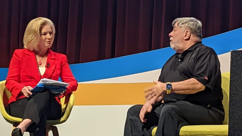
Later in the day came The Woz, here speaking with conference host Juanita Phillips:
Steve Wozniak (The Woz), Apple Co-Founder, and Juanita Phillips
Steve was a genuine engineer, taking joy in the machines he could build with the chipsets he played with. It was heartening to hear the desire to avoid conflict and disappointment, and focus on achievement and joy.
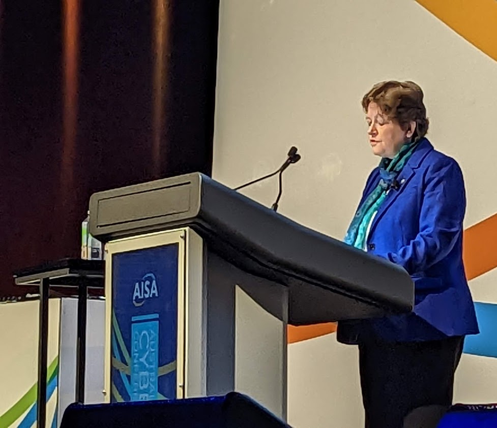
Next up was Juliette Wilcox CMG, Cyber Security Ambassador for UK Defence and Security Exports at Dept International Trade, UK Government.
Juliette Wilcox, UK Government
Juliette spoke well about the importance of strong cybersecurity, sharing advances, and having reliable systems to ensure that trade and economics could proceed smoothly.
The Hon Julie Bishop.
Next up was Julie Bishop, who also spoke about the important of strong cyber security in our digital systems and the reliance on these systems for international trade and relations.
Julie Bishop
Next up was environmental advocate (not activist), Erin Brockovich.
Erin Brockovich
Erin spoke of her stick-to-it-ivness, determination to write a wrong, and managing conflict. She rejects the title of being an Environmental Activist, as its deemed to negative, but more an advocate for the environment.
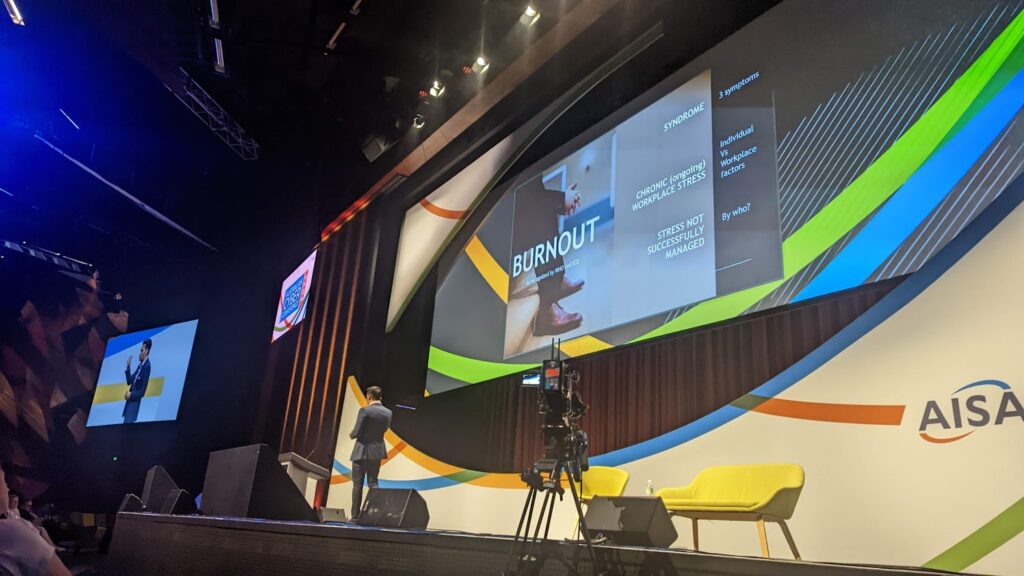
Dr Vyom Sharma
Next was Dr Vyom Sharma, talking about managing stress. From Workload, to Reward, Fairness, Autonomy, Community and Values as all being factors in stress that lead to burnout.
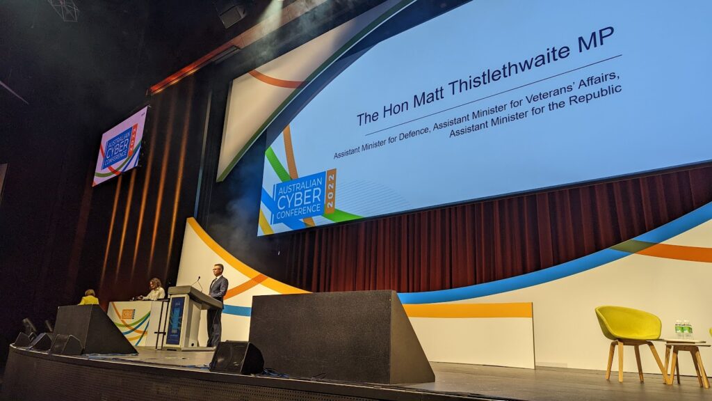
The Hon Matt Thistlethwaite, MP
A surprise was Matt Thistlethwaite adding to the line up, who spoke about the Dept Defence programs on Critical Infrastructure and reach out via ACSC and their programs.
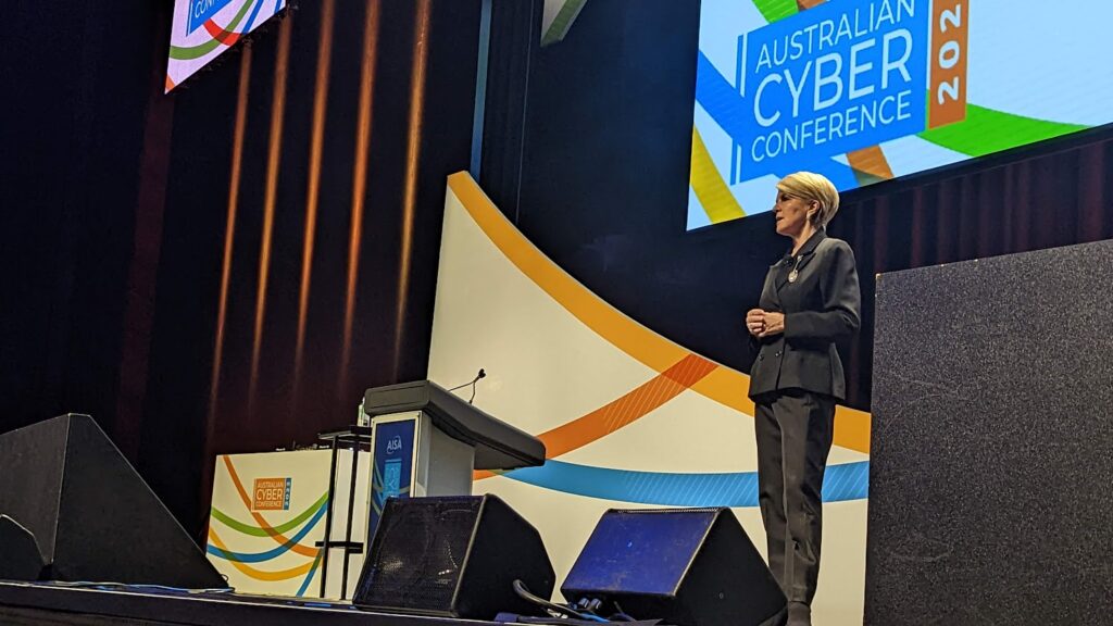
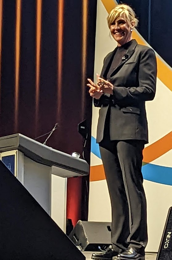
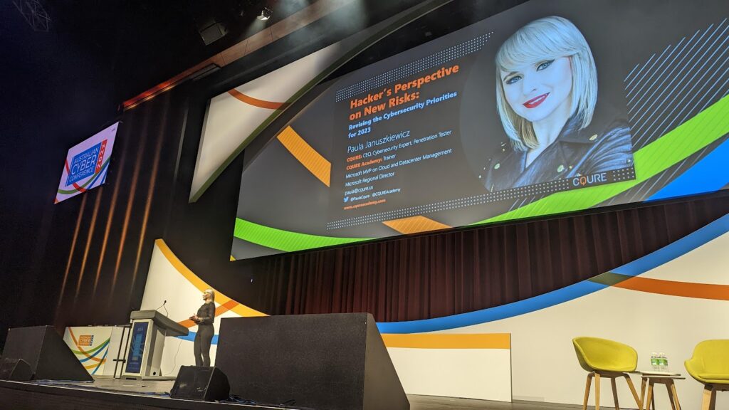
Paula Januszkiewicz
Finally a pentester gets to the stage – Paula J – who proceeded to drive holes with Windows Server processes and WMI, demonstrating live to the audience the risks with misconfigured and under-configured systems.
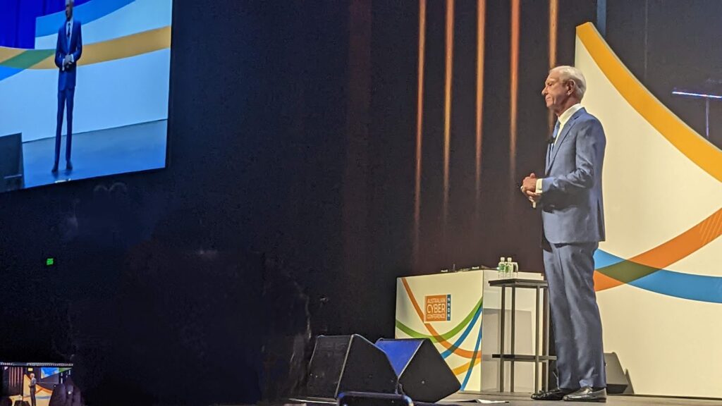
And then, we came to Capt Sully Sullenberger:
Capt Sulley Sullenberger
Capt’n Sulley was the calmest person on stage. He spoke about being passionate about what you love, and becoming a master of it. He says he’s loved two aircraft, and old DC, and the Boeing he was in when he encountered the bird strike in 2009 on flight 1529 our of New York. His passion meant that he had internalised the entire manual, and know which pages he would be turning to, and what the first few actions would be before any manual was opened.
He spoke of his roles and activities since 2009, working with aviation safety, and the improving record on US domestic flights (no deaths since 2009).
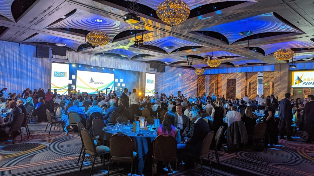
The Awards Dinner
As a speaker, I had a ticket to the awards gala dinner.
AISA Awards Gala Dinner, Crown Towers
It was great to see my local North Metro TAFE pick up one award, and Chris Bolan and friends at Seamless Intelligence pick up another. Congatulations to all the nominees and the winners.
A few sessions of note
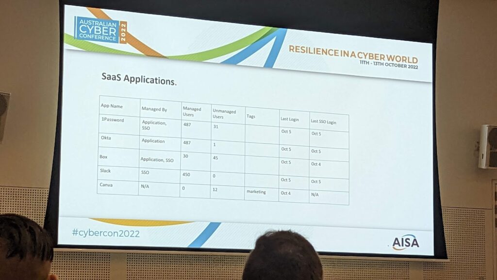
I kind of liked the presentation on Cyber Asset Attack Surface Management, new in the Gartner graphs of wonder from July 2021 . At its core, its about having more visibility of all the assets, including those SaaS apps that staff sign up for, and at its most basic, can be just a spreadsheet of what’s in use:
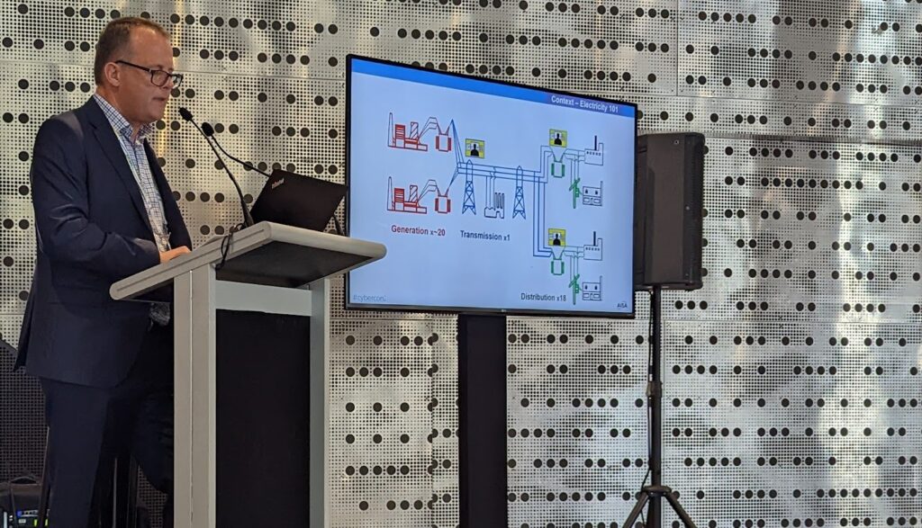
Next up, was the Ukranian power outages of 2014:
This was a remote access tool, where by engineers would see their mouse cursor moving and keystrokes being entered, but then custom firmwares flashed onto PLCs, turning the lights out for three regions of Ukraine. Power company staff had to drive to the remote sub stations to physically turn power back on, as all remote operations was lost.
The company had firewalls and VPN services in place, but clearly not strict and restricted enough to block this behavious – let alone network segregation (air-gap).
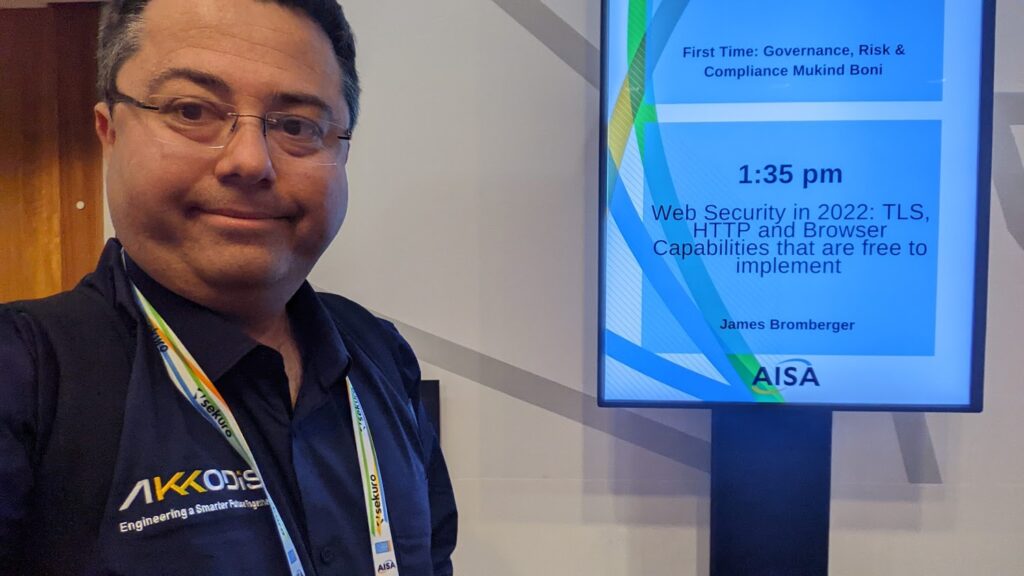
Of course, my session:
James Bromberger, about to go in and presentJames Bromberger presenting at CyberConf 2022, thanks to Kelly Taylor
Another session (no pics) spoke about securing domains (something I look to tools like Ivan Ristic’s hardenize.com). A new (minor) record to add to DNS is the BIMI record, to indicate the marketing icon (square SVG) to be displayed to users for authenticated mail from your domain. Personally I see that as just another record that a typo-squatting domain could just copy and use as well, so wont actually elevate security, but it was a new one for me (
But my highlight was meeting Cricket Liu, the author of the original DNS & Bind O’Reilly book.
James Bromberger & Cricket Liu
Cricket spoke about the 30 years tha have passed since then, and the more recent use of Resource Policy Zones in DNS to provide blocking and logging of DNS queries for malicious domains – including generated domains that are registered and activated at particular times to be Command & Control services for botnets. With Bind (and alternatively products from his company) you can easily share the policies to block these services, IMHO akin to the capability now in AWS GuardDuty and AWS DNS Firewall. We also spoke about DNS over HTTPS, DNSSec, and more.
But this discussion was by far and away the best of the conference for me. DNS is such a critical piece of our network engineering, and in so many environments its set up, works, and is then ignored; despite the fact that it is feasible to exfiltrate data (20 bytes at a time) over DNS – probably with millions of requests – but that will probably be invisible to most network operators.
It appears the team implementing their APIs did not have the skills to apply authentication, firewalling, rate limiting, alerting, and/or simulated data in non-production environments. It appears the management for this team did not know or enforce these protections either. And it appears the upper management did not check that lower management was taking necessary precautions and standards when handling PII.
There’s going to be some implications for this. Perhaps better engineering will be one of them.
I’m in the breach data as an Optus customer, and after a few days of news items, I received a confirmation email from Optus.
I’ve seen that in NSW, the digital-savvy minister Victor Dominello is already discussing re-issuing drivers licences in NSW. I thought I’d call the Western Australian Department of Transport and see what they are doing.
It’s been a public holiday Monday this week, so on Tuesday after 55 minutes in a queue, I got through to someone at DoT. Of course, to authenticate me on the phone they asked for the same information as shown in the data breach.
I learned:
DoT WA are not re-issuing licences at this stage
the ID number o the licence cannot currently be changed – it is perpetual
if they were to re-issue them with the same ID but a new expiry date, it would be on the same day and month, but 5 years later, so for any attacker trying a combination, the correct expiry date is the one in the breach, plus one, two, three for our five years.
The WA Department of Transport needs to look at this issue and fix a few items: The ID number issued to the public should be temporary and rotating for every issuance. I suspect there’s a few databases with this public number as a primary key. Perhaps the expiry date will need to be investigated to have 5 years +/- 30 days or so, and every re-issue should include the same variance. Indeed, perhaps reduce the lifetime from 5 years to two years to force rotation of the ID number, or let customers pay for the number of days they would like pro-rata, from 180 to 3650.
I know a few people at the Department, and I know they’re going to get a lot of focus from this issue. They’re welcome to reach out and chat with me; they have my details, after all. I know its a busy week for my contacts, so for anyone else out there, let’s stand back and wait.
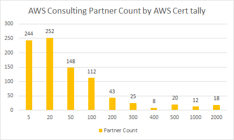
There some 937 partners listed today (25 July 2022) on the AWS Partner Finder who are Consulting Services Partners. Summing together shows around 102,189 AWS Certifications held by there consulting partners (as a minimum), for an average of 115 certifications each.
Some partners show zero certifications, and 244 listed partners have less than 20 AWS certifications in the organisations. 18 organisations are massive with over 2,000 certifications held.
AWS Consulting Partners by AWS Cert tally
As you can see from the graph, after you graduate your Consulting organisation past the 100-199 bucket, the numbers drop off quite markedly; just 126 partners fit in the 200+ certification range.
This is an inexact science, and it will be interesting to review in six months’ time.